
Circuit boards are at the core of modern technology, driving everything from household gadgets like smartphones and microwaves to advanced industrial systems such as automated machinery and medical equipment. Despite their reliability, their intricate design makes them susceptible to occasional malfunctions. Physical damage, voltage fluctuations, or component failures can disrupt operations, causing costly downtime. Efficient troubleshooting is crucial to restoring functionality and ensuring the longevity of these systems.
This guide provides a comprehensive overview of troubleshooting circuit boards. It covers the importance of diagnostic accuracy, step-by-step instructions, voltage management, and key repair techniques to maintain overall system performance.
Why Circuit Board Troubleshooting Matters
Circuit boards are essential to the operation of electronic devices across industries. A malfunctioning board can incapacitate an entire system, leading to workflow disruptions and financial losses. Effective troubleshooting addresses immediate issues and prevents recurring problems, enhancing system reliability and durability.
Step-by-Step Guide to Troubleshooting Circuit Boards
1. Understand the Circuit Design
Begin by reviewing the circuit schematic, which outlines the components, their connections, and the board’s functionality. This document acts as a roadmap, guiding you through power distribution and signal flow. Familiarity with the schematic allows for faster identification of potential failure points.
Key Benefits of Schematic Review:
- Pinpoints areas likely to fail.
- Provides a baseline for expected behavior.
- Reduces time spent on guesswork during diagnosis.
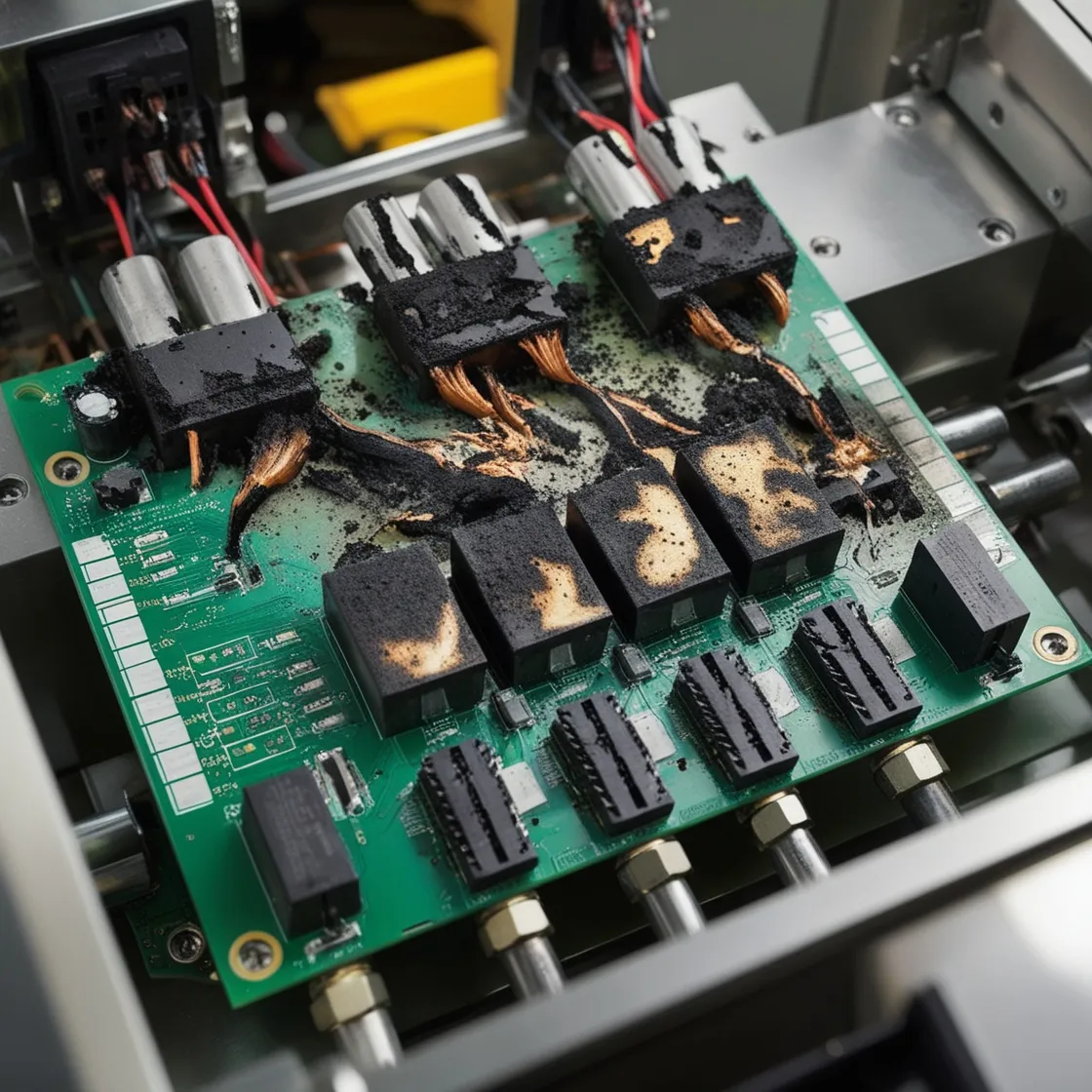
2. Inspect for Visible Damage
A thorough visual inspection can reveal obvious signs of damage. Look for:
- Burned traces or components:Often caused by overheating due to excessive current or voltage.
- Broken connections:Cracked solder joints or traces from physical stress or corrosion.
- Corrosion or wear:Environmental factors like dust or moisture degrade the board’s integrity.
Example: A burned resistor might indicate excessive voltage but could result from a deeper issue, such as a faulty capacitor. Use the schematic to trace the problem back to its source.
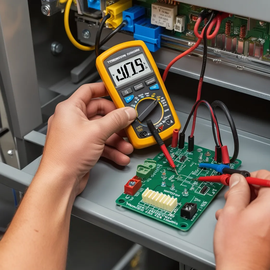
3. Measure Voltages with Precision
Using a multimeter, measure voltages at key points on the board. Compare these readings with schematic values to identify abnormalities.
Case Study:
A team troubleshooting an oscilloscope discovered abnormal voltage in the vertical deflection amplifier. By tracing the issue, they identified a faulty transistor. Replacing it restored functionality, demonstrating the effectiveness of voltage analysis.
4. Apply Logical and Systematic Reasoning
Approach troubleshooting like a detective solving a case:
- Form Hypotheses:Use circuit knowledge to predict failure points.
- Test Methodically:Validate or eliminate causes step by step.
- Avoid Random Replacements:Swapping components arbitrarily can worsen issues or waste resources.
5. Address Proprietary or Complex Boards
Troubleshooting boards without schematics can be challenging. Options include:
- Consult Experts:Specialized repair services can offer diagnostics.
- Replace Boards:If repair isn’t feasible, replacing the board ensures system stability.
Managing Voltage Limits in Circuit Boards
1. Voltage Ratings and Component Protection
Each component operates within a specified voltage range. Exceeding these limits can damage sensitive parts, like transistors and motors. Adhering to voltage thresholds ensures performance and longevity.
2. Voltage Zones on Circuit Boards
- High-Voltage Areas:Handle up to 250V, crucial for power conversion.
- Low-Voltage Areas:Operate at 4V to 7V, requiring surge protection to prevent damage.
3. Input and Output Voltage Management
- Input Voltage:Stay within limits to avoid system-wide disruptions.
- Output Voltage:Protect against external fluctuations using diodes or resistors to stabilize voltage levels.
The Role of Circuit Boards in Electronic Systems
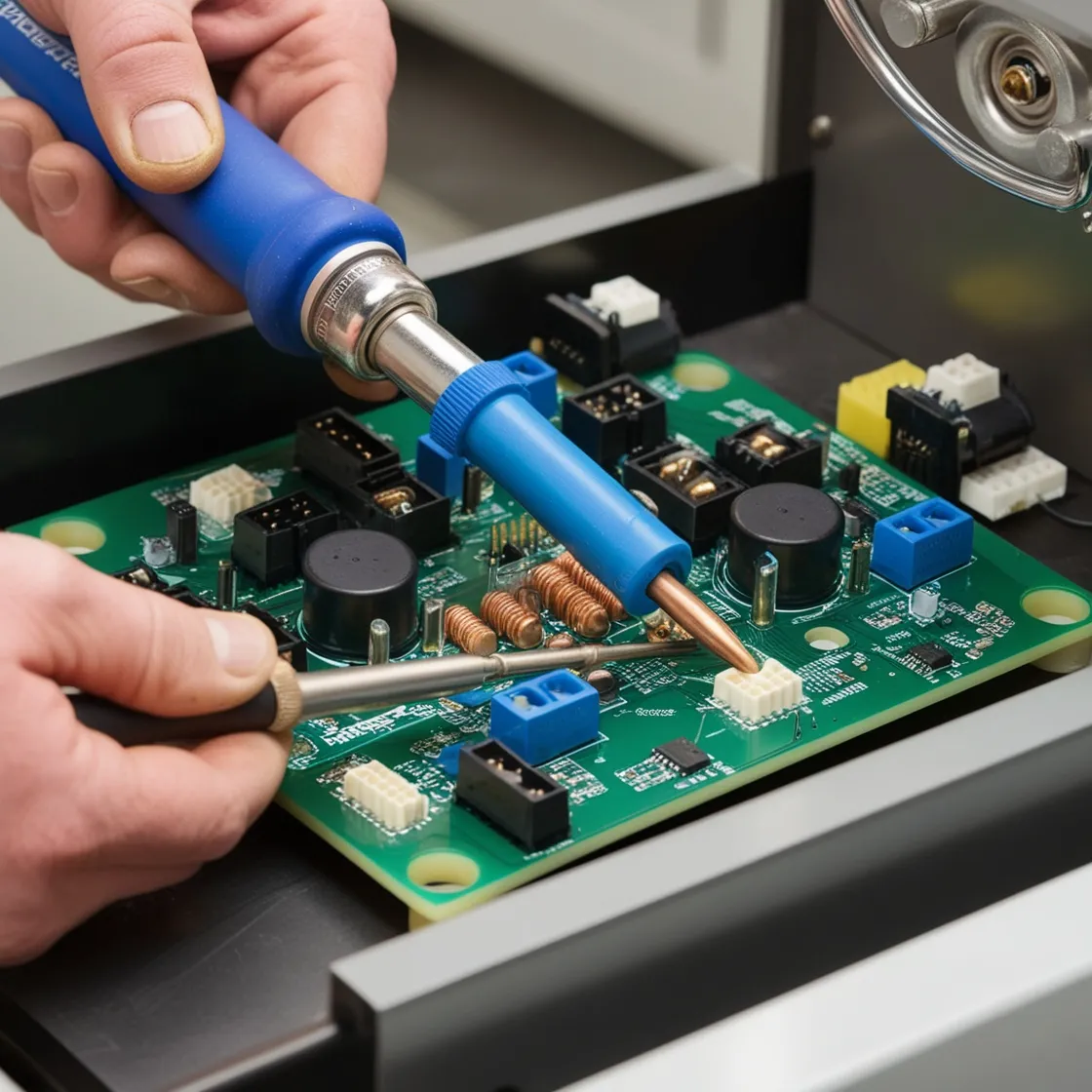
1. Supporting Components and Connectivity
Conductive traces and soldered joints ensure stable connections, vital for system reliability. This is especially important in compact designs where optimal performance is critical.
2. Signal Transmission and System Integration
- Standalone Boards:Operate independently within devices, handling specific tasks.
- Integrated Systems:Use backplanes or wiring harnesses to connect multiple boards, optimizing system-wide performance.
3. Material and Design Diversity
Circuit boards are tailored for different applications:
- Rigid Boards:Durable and reliable for standard systems.
- Flexible Boards:Adaptable for confined or dynamic environments.
- High-Performance Boards:Designed for demanding conditions with enhanced heat dissipation.
Conclusion
Mastering circuit board troubleshooting combines technical expertise with logical reasoning and systematic methods. A thorough understanding of circuit design, voltage management, and component interactions is key to diagnosing and resolving issues efficiently. By adopting structured troubleshooting strategies, technicians can minimize downtime, extend system life, and restore functionality, ensuring modern devices continue to operate reliably.
